
The idea to create a type of close proximity radar system came from a student in one of my classes. We went ahead and decided to streamline the idea into the course as one of the projects we'd build.
After a week or two of prep time we finally agreed on the project setup & parts that we'd use. This is not meant to be an advanced project, thusly the difficulty is set at medium.
Below is an example of what short range personal radar could be used for. It's meant to be a bit comical so feel free to laugh!
Purpose & Overview of this project
The goal of this project is to create a working ir radar system. The system will only be required to measure close proximity at an angle of 90 degrees as seen in the example above. The range of system is roughly 4-30cm, 20-150cm & 1m-5.5m depending upon which sensor you choose to use.
The outcome of this project will shape future projects where we try to integrate such a radar system to help navigate mobile robots through the real world.
Parts List Details
You may or may not be familiar with the parts above so a picture of each item has been included to help give you an idea of what they look like. Three new objects that we've never seen before appear in this project; Servos, the74HCT373 & IR Sensors. Tutorials on Servos & IR Sensors should be up soon but for the 74HCT373 I've given a brief overview of it below. You can always check out the datasheet for the chip by search google for "74HCT373".
The 74HCT373
This chip is an octal d flip-flop tri-state latch. In english that means that this chip is capable of storing 8 bits of digital logic and holding that memory until it is cleared or changed via the LE-Latch Enable pin.
How It Works
•Control Pins LE & OE
•8 Data Inputs D0-D7
•8 Data Outputs Q0-Q7
•Vcc & GND.
Output Enable allows Q0-Q7 to output the data currently held in the D-FlipFlop Latches.
Latch Enable enables the data currently on D0-D7 to overwrite whatever the D-FlipFlop Latches currently have.
Schematic Overview
The schematic for this project is much more complicated than previous projects. There are four main features in our design. (1) We will be able to program the pic on the board we develop. (2) We will be controlling a servo. (3) We will be taking data input from an IR Proximity sensor. (4) We will set 36 LEDs to display proper output to respresent what the IR sensor sees.
View Full Schematic
Schematic Specifics
•Power Circuit
The power circuit is a 9v Battery hooked up to the LM7805 with a 1uF capacitor hooked to output & ground of the LM7805 to keep a steady 5v DC.
•Programming Circuit
The programming circuit is made by hooking up two pins from the PIC to the programmer and allowing the programmer's pin 1 access to the MCLR*/Vpp-Pin1 on the PIC. We put a rectifier diode in there for safety as well.
•IR Proximity Sensor
The IR Sensor only uses 1 pic from the pic, PIN 2 - RA0. It will use the analog feature of this pin to get an ADC value as the proximity sensor only outputs analog voltages. This value will tell us the if anything is near the sensor in our enviornment.
•LEDs Output
There are 40 LEDs in total. Since each 74HCT373 can control up to 8 leds; 40/8 = 5 we'll need to use 5 74HCT373's to be able to control all 40 LEDs. It is important to notice on the schematic that a common data bus is used between all the 5 chips.
The Theory
This project uses three main devices to create the personal radar system. The IR Range sensor gives output, the pic microcontroller processes it and then displays the output on the led array. Here is a simple little animation that demonstrates this:
Using Different Sensors
An interesting thing about the sharp IR sensors that I've used in this project is that they all follow the same voltage curve so one program can literally fit all sensors. You only have to be aware of the sensor that is being used to make sense of the distance output by the leds.
Our Implementation
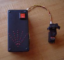
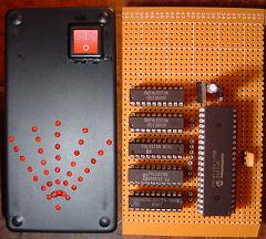
We just got a brief high-level overview of the theory, for more indepth explainations of the theory please go back to any of the tutorials (pic, servos orir sensors). Now let's take a look at the finished hardware device:
This is how the device looks when it is completed. So let's move onto the next section and actually assemble the schematic on the proto board and build the hardware enclosure.
Hardware Design
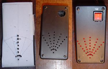
The plastic enclosure seen below wasn't mentioned in the parts list. It's just a generic enclosure you can buy from any electronics distributor or manufacturer.
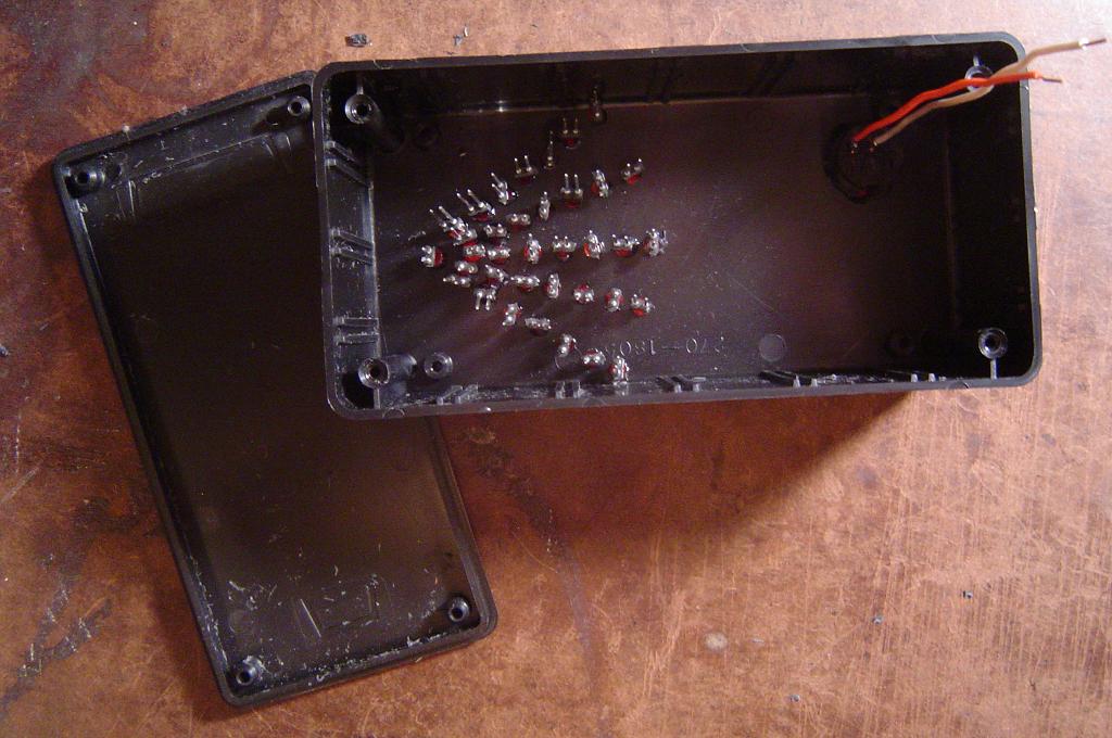
The first thing we need to do is to drill holes for all the 36 leds that will be in our circuit and to e-poxy the leds into them. Additionally I put a little epoxy on led leads before sticking them into sip sockets so they'd stay on.

Now we'll get the board soldered in and start to wire-wrap the schematic. You should be able to fit all the ic's onto the board in a small enough space to fit into your enclosure.
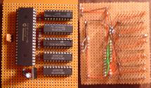
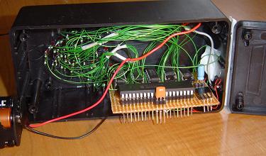
The above picture is a sample of how the board should look during initial stages. Once you have everything wirewrapped it will be quite a mess of wires but should look something like this:
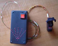
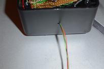
The final look at the hardware design is what allows the personal radar system to be used 'remotely'. We use a length of wire about 2-4 meters long when connecting the servo & ir sensor. We put a hole in the front of the enclosure for these wires:
With the hardware completed lets move onto the software portion of the project. This is definitely the funner part of this project, nore more soar fingers from wire-wrapping.
The Software
The IR range software for this project has three main portions to it.
-Servo Control
-Led Output Control
-A/D Input
Since the software for this project won't fit all on one page I'll explain these three elements and how they're implemented. If you have any lasting questions about the software just go to the forums and ask! The program is heavily commented so it should be readable.
Servo Control
The method used for servo control is via timers & interrupts. A 50Hz signal is generated by two seperate interrupts that work together to create desired pulses that make the servo pan left and right in small steps so as to quiet the servo's squeaking movement noise.
Led Output Control
The leds are all controlled via the 74LS373/74HCT373 latches. The pic inturn controls these devices by switching the control lines. The system constantly updates the latch information which can be seen by the led output.
A/D Input
The IR range sensor output is in the form of a varying analog voltage. We use the a/d converter to find the value of this voltage which will tell us the distance that objects are away from the ir range sensor.
Software loaded & hardware completely built. Let's test it out! Depending on the sensor you use, different output will be visible on the leds. Sensors to choose from: GP2D120, GP2Y0A21YK or GP2Y0A700K0F.
Data & Observations
The first test of the personal radar system will be close range. I used rockstar energy drink cans as obstacles. (These IR sensors work best when objects are all white.)
The second video (which was seen on the first page) tests out the 20cm-150cm & 1m-5.5m sensors which allow for funner things than rockstar can obstacles. Watch and you'll see what I mean:
These two videos give you a good idea of how well the sensor can work, however if you build it yourself you'll see a few shortcoms which I'll discuss in the conclusion.
Program Download:
Main C File
ir_range_project.c
An Overview Of The Personal Radar System
Building and programming this project doesn't take too terribly long. It is definitely a project that you can complete in a day and it has some viable uses but in the long run there are many shortcommings that arise from using this form of radar. IR sensors can become unreliable and rarely output constant results because of ambient and enviornmental light.
What To Do Now
If you really want to improve upon this form of radar a good area to explore would be the use of ultrasonic sensors. Ultrasonic sensors are the equivalent of above water 'sonar' sensors that will tell you the range an object is away from you. Ultrasonics have a greater range than Ir sensors and are typically far more reliable in unfamiliar enviornments.
Source: http://www.pyroelectro.com/projects/ir_radar/
Show us some love, like us on Facebook
After a week or two of prep time we finally agreed on the project setup & parts that we'd use. This is not meant to be an advanced project, thusly the difficulty is set at medium.
Below is an example of what short range personal radar could be used for. It's meant to be a bit comical so feel free to laugh!
Purpose & Overview of this project
The goal of this project is to create a working ir radar system. The system will only be required to measure close proximity at an angle of 90 degrees as seen in the example above. The range of system is roughly 4-30cm, 20-150cm & 1m-5.5m depending upon which sensor you choose to use.
The outcome of this project will shape future projects where we try to integrate such a radar system to help navigate mobile robots through the real world.
Parts List Details
You may or may not be familiar with the parts above so a picture of each item has been included to help give you an idea of what they look like. Three new objects that we've never seen before appear in this project; Servos, the74HCT373 & IR Sensors. Tutorials on Servos & IR Sensors should be up soon but for the 74HCT373 I've given a brief overview of it below. You can always check out the datasheet for the chip by search google for "74HCT373".
74HCT373
This chip is an octal d flip-flop tri-state latch. In english that means that this chip is capable of storing 8 bits of digital logic and holding that memory until it is cleared or changed via the LE-Latch Enable pin.
How It Works
•Control Pins LE & OE
•8 Data Inputs D0-D7
•8 Data Outputs Q0-Q7
•Vcc & GND.
Output Enable allows Q0-Q7 to output the data currently held in the D-FlipFlop Latches.
Latch Enable enables the data currently on D0-D7 to overwrite whatever the D-FlipFlop Latches currently have.
Schematic Overview
The schematic for this project is much more complicated than previous projects. There are four main features in our design. (1) We will be able to program the pic on the board we develop. (2) We will be controlling a servo. (3) We will be taking data input from an IR Proximity sensor. (4) We will set 36 LEDs to display proper output to respresent what the IR sensor sees.
View Full Schematic
Schematic Specifics
•Power Circuit
The power circuit is a 9v Battery hooked up to the LM7805 with a 1uF capacitor hooked to output & ground of the LM7805 to keep a steady 5v DC.
•Programming Circuit
The programming circuit is made by hooking up two pins from the PIC to the programmer and allowing the programmer's pin 1 access to the MCLR*/Vpp-Pin1 on the PIC. We put a rectifier diode in there for safety as well.
•IR Proximity Sensor
The IR Sensor only uses 1 pic from the pic, PIN 2 - RA0. It will use the analog feature of this pin to get an ADC value as the proximity sensor only outputs analog voltages. This value will tell us the if anything is near the sensor in our enviornment.
•LEDs Output
There are 40 LEDs in total. Since each 74HCT373 can control up to 8 leds; 40/8 = 5 we'll need to use 5 74HCT373's to be able to control all 40 LEDs. It is important to notice on the schematic that a common data bus is used between all the 5 chips.
The Theory
This project uses three main devices to create the personal radar system. The IR Range sensor gives output, the pic microcontroller processes it and then displays the output on the led array. Here is a simple little animation that demonstrates this:
Using Different Sensors
An interesting thing about the sharp IR sensors that I've used in this project is that they all follow the same voltage curve so one program can literally fit all sensors. You only have to be aware of the sensor that is being used to make sense of the distance output by the leds.
Our Implementation
We just got a brief high-level overview of the theory, for more indepth explainations of the theory please go back to any of the tutorials (pic, servos orir sensors). Now let's take a look at the finished hardware device:
This is how the device looks when it is completed. So let's move onto the next section and actually assemble the schematic on the proto board and build the hardware enclosure.
Hardware Design
The plastic enclosure seen below wasn't mentioned in the parts list. It's just a generic enclosure you can buy from any electronics distributor or manufacturer.
The first thing we need to do is to drill holes for all the 36 leds that will be in our circuit and to e-poxy the leds into them. Additionally I put a little epoxy on led leads before sticking them into sip sockets so they'd stay on.
Now we'll get the board soldered in and start to wire-wrap the schematic. You should be able to fit all the ic's onto the board in a small enough space to fit into your enclosure.
The above picture is a sample of how the board should look during initial stages. Once you have everything wirewrapped it will be quite a mess of wires but should look something like this:
The final look at the hardware design is what allows the personal radar system to be used 'remotely'. We use a length of wire about 2-4 meters long when connecting the servo & ir sensor. We put a hole in the front of the enclosure for these wires:
With the hardware completed lets move onto the software portion of the project. This is definitely the funner part of this project, nore more soar fingers from wire-wrapping.
The Software
The IR range software for this project has three main portions to it.
-Servo Control
-Led Output Control
-A/D Input
Since the software for this project won't fit all on one page I'll explain these three elements and how they're implemented. If you have any lasting questions about the software just go to the forums and ask! The program is heavily commented so it should be readable.
Servo Control
The method used for servo control is via timers & interrupts. A 50Hz signal is generated by two seperate interrupts that work together to create desired pulses that make the servo pan left and right in small steps so as to quiet the servo's squeaking movement noise.
Led Output Control
The leds are all controlled via the 74LS373/74HCT373 latches. The pic inturn controls these devices by switching the control lines. The system constantly updates the latch information which can be seen by the led output.
A/D Input
The IR range sensor output is in the form of a varying analog voltage. We use the a/d converter to find the value of this voltage which will tell us the distance that objects are away from the ir range sensor.
Software loaded & hardware completely built. Let's test it out! Depending on the sensor you use, different output will be visible on the leds. Sensors to choose from: GP2D120, GP2Y0A21YK or GP2Y0A700K0F.
Data & Observations
The first test of the personal radar system will be close range. I used rockstar energy drink cans as obstacles. (These IR sensors work best when objects are all white.)
The second video (which was seen on the first page) tests out the 20cm-150cm & 1m-5.5m sensors which allow for funner things than rockstar can obstacles. Watch and you'll see what I mean:
These two videos give you a good idea of how well the sensor can work, however if you build it yourself you'll see a few shortcoms which I'll discuss in the conclusion.
Program Download:
Main C File
ir_range_project.c
An Overview Of The Personal Radar System
Building and programming this project doesn't take too terribly long. It is definitely a project that you can complete in a day and it has some viable uses but in the long run there are many shortcommings that arise from using this form of radar. IR sensors can become unreliable and rarely output constant results because of ambient and enviornmental light.
What To Do Now
If you really want to improve upon this form of radar a good area to explore would be the use of ultrasonic sensors. Ultrasonic sensors are the equivalent of above water 'sonar' sensors that will tell you the range an object is away from you. Ultrasonics have a greater range than Ir sensors and are typically far more reliable in unfamiliar enviornments.
Source: http://www.pyroelectro.com/projects/ir_radar/
Show us some love, like us on Facebook
 Posted in:

0 comments:
Post a Comment