
SparkFun Electronics:
You've got your MCP. You've got all the cables and a PIC to experiment with. It is time to start programming!
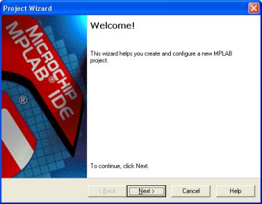
This tutorial will get you started using the MPLAB interface. We will walk you through the steps to get a 16F628 loaded up with the Blink.asm file.
You will need to download Blink.asm - remember where you stuffed it away, you'll need it later.
The greatest thing about the MCP is that it is a PICSTART+ look-alike. The guys at Microchip charge upwards of $200 for the PICSTART+! While the MCP that can do everything the PS+ is only $75. All the online information for the PS+ is also applicable for the MCP. So take a look around, MPLAB is a big burly development environment, but there is plenty of documentation on the Microchip website.
You will need to download the latest version of MPLAB (currently v6.20) from the Microchip website - don't worry, it's free.
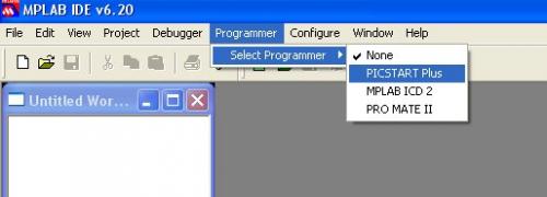
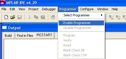
Get it installed and run the main MPLAB IDE v6.20 shortcut. Plug in the serial cable and power to your MCP and select the PICSTART+ from the programmer menu:
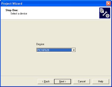
On the second window select the device that you will be using for this project. For our purposes, be sure to select the 16F628.
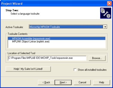
All of these defaults are fine - just click Next.
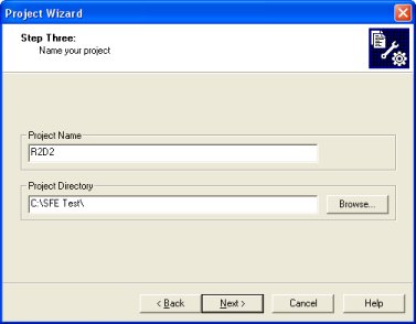
Give your project a creative Star Wars character name and working directory.
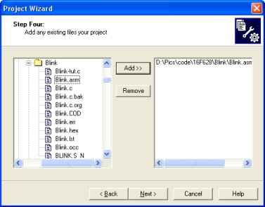
Now add the Blink.asm file to your project.
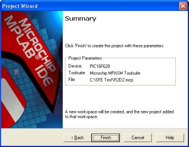
Now you should be all set!
After the wizard closes, you should have the MPLAB desktop again that should look like this:
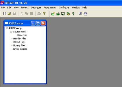
From here you can double click on the Blink.asm file to open it and edit it as you like. You can also change the configuration bits for any given project by going to Configure -> Configuration Bits.
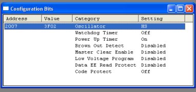
Here you can change the device specific settings such as the Watch Dog Timer, Oscillator speed, LVP, and code protection. The above settings are highly recommended for normal use.
Stay away for the Watch Dog Timer until you get really comfy with PICs. The Power Up Timer is fine. The Brown Out Detect is usually only needed in specific applications. The Low Voltage Program is not used because this is a tutorial for the MCP! And we don't really need to code protect the Blink program, do we?
Once you have fiddled with it you will need to re-build the project. Select the Build Allcommand under the Project menu.
MPLAB will run MPASM (acronym city) and your ASM file will become a HEX file if everything is good to go. If not the report window will give you errors and line numbers on which those errors occurred.
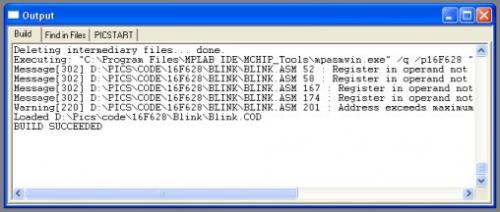
Here we see a compiling of BLINK.ASM. The reason for all of the warnings is because we used a C compiler (CC5x) and it does all of the register switching for us, so you can disregard these messages and warning. The main point here is the BUILD SUCCEEDED. We can now program the part!
Place the 16F628 at the top of the ziff socket with Pin 1 near the arm of the socket. Don't forget to lock the socket!
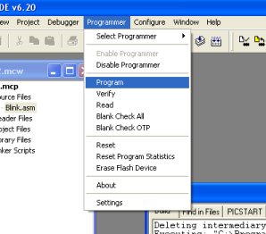
Now select Program.
Lights will blink - progress bars will advance. In the end you should get a window telling you the results:
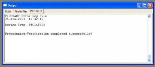
Everything was successful. But that took a really long time! Why? Blink.asm is tiny.
The reason is the MPLAB programs the entire programming space and the EEProm space by default. To really see what's going on (this gets ugly), under the View menu, select Program Memory. You should get a big window full of gibberish.
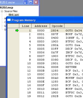
This is a listing of all the opcodes or the actual machine code that got loaded onto the PIC. From here you can change opcodes by hand. Kinda crazy, but you could even program like this if you so desired. All we care about is where our program ends. Scroll down a ways until everything turns to 3FFF.
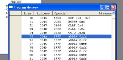
As you can see, our program ends very very early on at hex 0x004A. So why is MPLAB programming all of the chip and the eeprom? Let's make it stop!
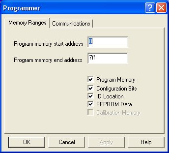
Under the Program menu, select Settings. You will then be allowed to change where the program begins and ends. Be careful. One day you may run into a really weird error that will boggle you for hours just to find out that you've only been programming part of your PIC. For this tutorial, set the end address to 050 and deselect EEPROM Data.

Click OK. Now go to the Programmer menu and select Program.
*Tutorial take from SPARKFUN ELECTRONICS website, only for educational purpose.
 Posted in: MPLAB IDE; PIC programmer

0 comments:
Post a Comment