
Introduction
We created a wearable game controller that uses accelerometers to acquire action of the hand and then maps an action to an arbitrary keystroke. The types of actions we are trying to recognize should be suitable as input control for video games.
We placed 3 z-axis accelerometers on tips of the thumb, the index finger and the middle finger, and three accelerometers on the back of the hand for x,y, and z acceleration. The Atmega644 microcontroller read the output of the accelerometers and simulates a finite state machine to compute the gesture and the motion of the hand. The gesture and motion information is then transmitted to PC through serial connection, and a Java program is used to read the information and map it to an arbitrary keystroke.
High level design
Rationale
Some current game controllers such as the Wii remote take use of sensors and are capable of using the player’s motion as input, to some extent. However, none of the controlling method can take advantage of the expressibilities of natural gestures. As avid gamers, we determined that a hand-action-based controller would be a novel and fun input device.
By observation, we have found that many meaningful actions performed by a hand (e.g. smash, swing or push) can be described by the hand gesture and the movement of the palm. Furthermore, the hand gesture should be independent with the hand movement and orientation, but can only be changed from one to another by movements of fingers. On the other hand, the orientation is only dependent on the movement of the hand. Therefore in our project, we propose a prototype of real time hand action recognition by 8-bit microcontroller using acceleration data from finger tips and back of the hand.
Background Math and Physics
Accelerometers: the accelerometers we used measures acceleration from a capacitive sensing cell (g-cell) which forms two back-to-back capacitors. As shown in Figure 1, when the center plate deflects due to acceleration, the value of capacitors will change and acceleration data can be extracted.

Figure 1: Physical Model of the Accelerometer
Each accelerometer’s reading consists of dynamic acceleration and static acceleration, namely the gravity. For a z-axis accelerometer placed flat, Figure 2 shows the sign of the reading. The static acceleration is +1g, where as the dynamic acceleration reading is positive if the direction of the acceleration is upward.
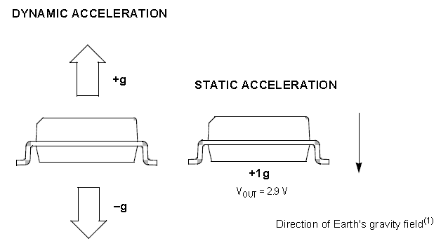
Figure 2: Sign of Measurement of the Accelerometer
By placing three accelerometers on the back of the hand, we set up a coordinate system. If the hand is still, we can measure direction of the hand plane. Moreover, if the finger moves slowly, then at each reading its acceleration are mostly due to gravity.
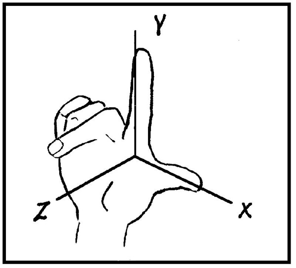
Figure 3: Hand Coordinate System
If the hand moves very rapidly, the process is a sequence of acceleration-deceleration. Therefore the output will show a large peak and afterwards a peak with opposite sign. Figure 4 shows the z-axis acceleration output when a hand suddenly moves downward and goes back.
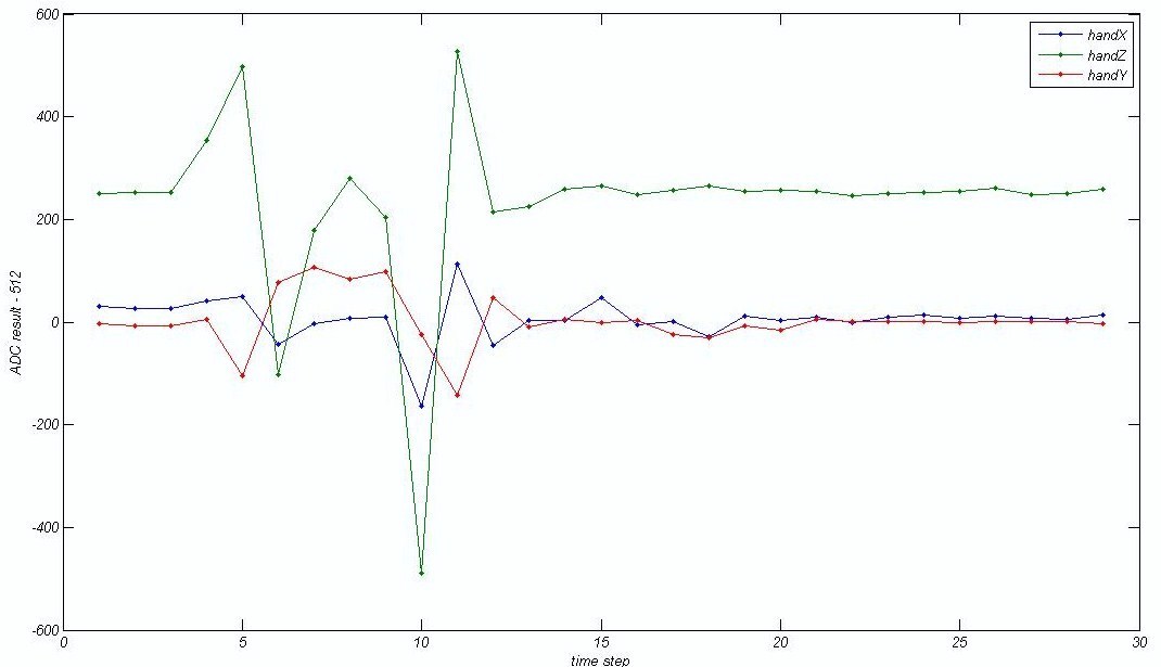
Figure 4: Accelerometer Output for moving Hand
Logical structure
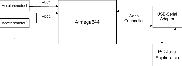
Figure 5: Logical Structure
The high level design of our project is shown in Figure 5. This diagram shows the flow of data from when the user end Java Application opens the port for communication to when then information is transmitted to the Application and mapped to a keystroke.
Hardware/Software Tradeoffs
One of the major limitations for our project is the functionalities of the accelerometers. Limited by budget, available materials and soldering technique, we only used one-axis low-g analog accelerometers. Although these accelerometers require simpler hardware and software than a digital or multi-axis accelerometers does, their outputs are very noisy. In addition, they have a measurement range of only 1.5g, meaning that fast movements will cause the output to reach the rails. It is difficult to integrate the acceleration to get velocity, not to mention position. However, we applied several techniques to reduce the noise and were still able to acquire much useful information from the accelerations. Specifics are covered in Software and Hardware sections.
Another tradeoff is expandability of the system versus usability. We cannot hard code every possible action. However, adding more actions meaning adding states in the state machine, which poses a difficulty for the user. We have to define a system that is ready to go, but can also be easily expanded.
Hardware Design
Our hardware consists of three parts: the custom PCB for Atmega644, the accelerometer circuit, and the Pololu USB AVR programmer, which we used as the serial connection between PC and the custom PCB. Schematics for all hardware can be found in the Appendix III: Hardware Schematics.
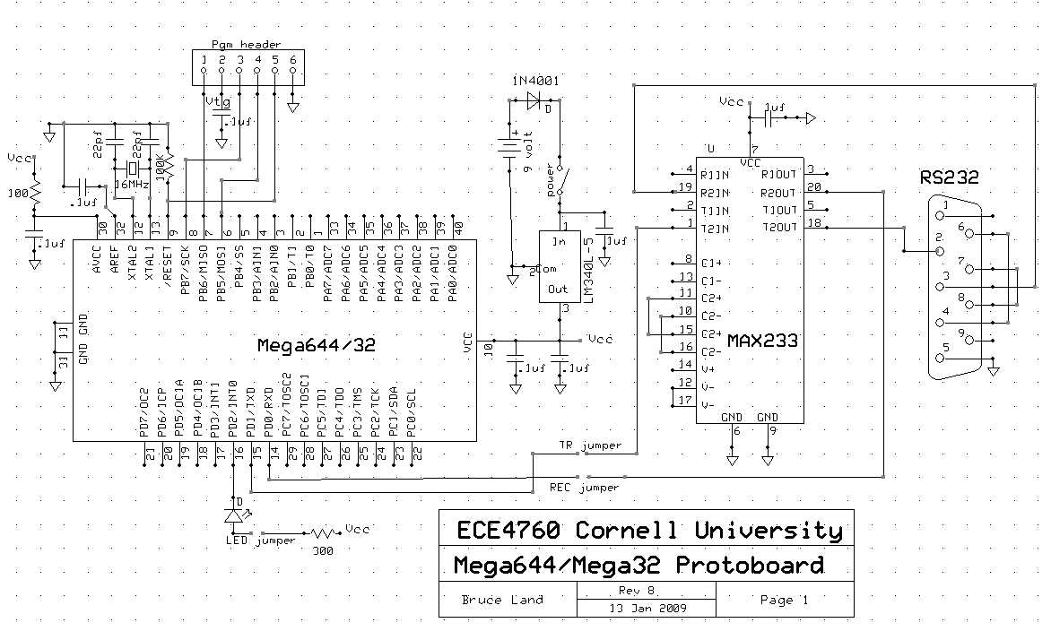
ECE 4760 Custom PCB
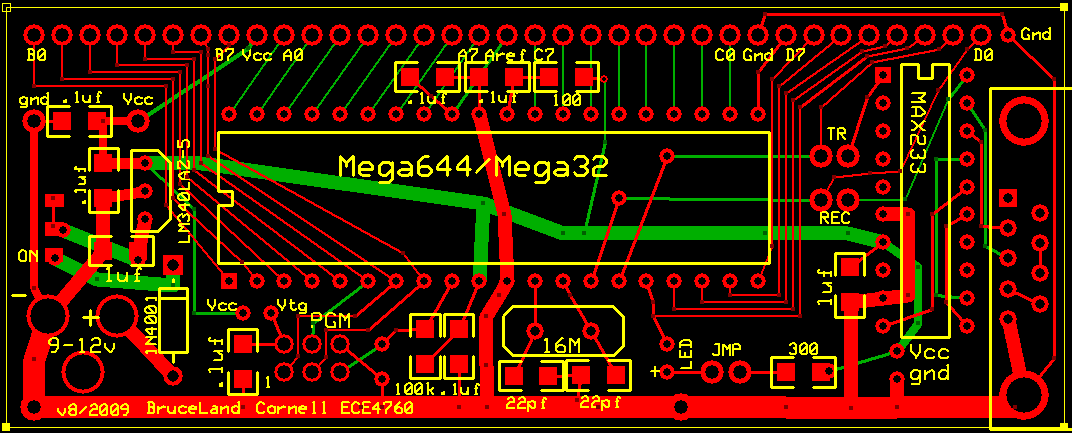
We used the custom PCB designed by ECE 4760 instructor Bruce Land to interface Atmega644 with our circuits. The board design is shown in Figure 6 and the layout is shown in Figure 7.
Accelerometer
The accelerometer circuit consists of four MMA1260D z-axis analog accelerometers, three MMA2260D x-axis analog accelerometers, and the external circuit, which consists of decoupling capacitors and low pass filtering circuits as the datasheet of MMA1260D and MMA2260D suggests. From our tests, the circuit decreased the magnitude of the noise in the output by 0.03V, which is desirable. The schematics are shown in Figure 8.
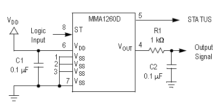
Figure 8: ADC Circuit for Accelerometer
The accelerometers are connected to Pin A of the MCU for ADC, and the reference voltage is set to Vcc. The correspondence of the accelerometers and the pins are shown in the following table:
| Accelerometer Type | Position | Pin |
|---|---|---|
| Z-axis | Thumb | A.0 |
| X-axis* | Back of the Hand | A.1 |
| Z-axis | Index Finger | A.2 |
| Z-axis | Back of the Hand | A.3 |
| Z-axis | Middle Finger | A.4 |
| X-axis* | Back of the Hand | A.5 |
Table 1: Accelerometers-pins
*Note: Although both accelerometers are X-axis, we let them measure different axis by orienting one 90 degrees away from another. See picture below for details.
USB-to-Serial Adaptor
We used a Pololu USB AVR programmer as the USB-to-Serial Adaptor. The programmer contains two control lines, TX and RX, used to send asynchronous serial communication. When the programmer receives one byte from USB, it transmits one byte on TX. The lines transmit data 8 bits at a time with no parity and one stop bit. It looks like a standard serial port to operating system, so it can be accessed from serial port functions.
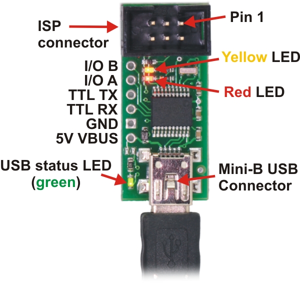
Figure 9: Picture and Schematics of the Pololu USB AVR Programmer
Software Design
Our program naturally consists of two parts according to the logical structure: hand action recognition codes for the MCU and PC end application. Different aspects of the software are described below in details:
Hand Action Recognition
The action recognition code makes up most of the code for the MCU. We used a state machine design for our program. With the acceleration data from the six accelerometers, we are able to acquire several pieces of information: hand motion, hand orientation, and each finger’s status. The input to the state machine is all these information combined. Each state corresponds to an action, and the new state depends on the current input and the current state. The figure next summarizes the program structure:
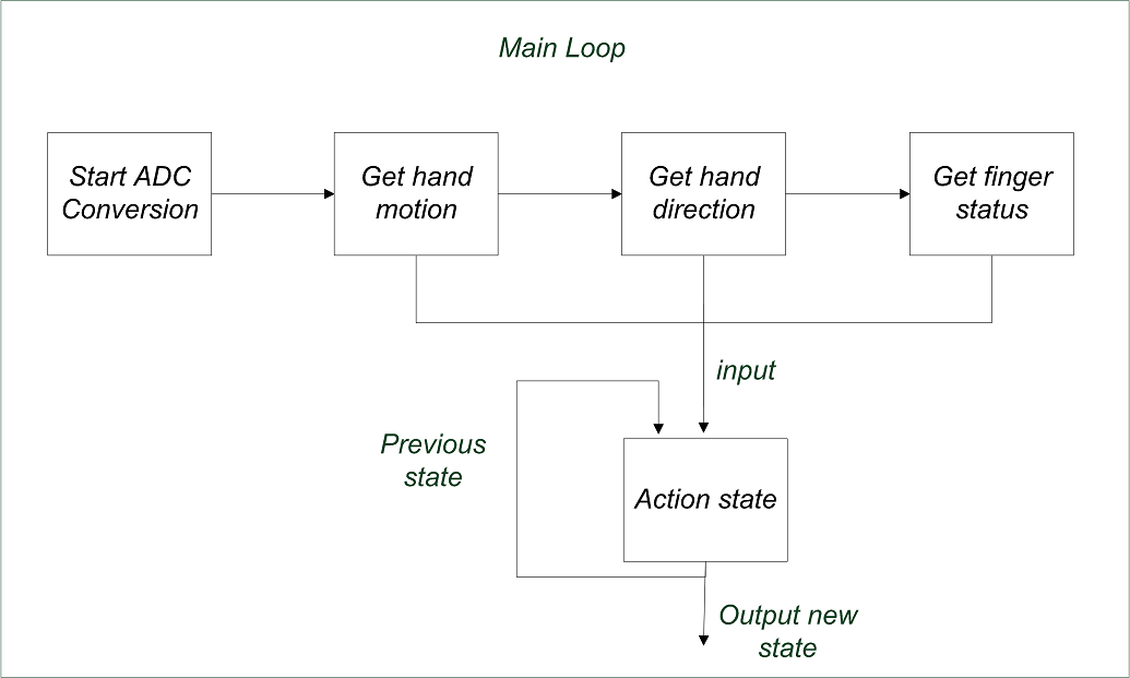
Figure 10: Program Structure
1) Analog-to-digital Converter
We used the analog-to-digital converters on Atmega644 to obtain acceleration measurements from the 6 accelerometers. For an accelerometer, V_OH=5V,V_OL=0V, so we chose V_cc(5V) as the reference voltage. We took all 10 bits that VDC read and subtracted by 512 as an acceleration value, which would be in the range [-512, 512].
During every loop of execution, each of the input ports is read in turn by incrementing ADMUX, the ADC input select register. Before beginning a conversion, we wait until the last conversion is done, i.e. the ADSC bit is set high.
2) Raw Data Treatment
We need to convert raw acceleration data to three pieces of useful information: hand motion, hand orientation, and status of each finger. As explained in the hardware tradeoff section, the acceleration data acquired is noisy, which must be taken care of when we extract information about the hand’s action.
In order to reduce the effect of noise, we decided to set a small noise threshold and a large peak threshold. After trial and error we set noise threshold = 50 and peak threshold = 150. Oscillations smaller than 50 are regarded as caused by noise and are suppressed, whereas oscillations larger than 150 are detected as peaks, indicating a rapid motion. Figure 11 shows the acceleration data of a moving finger.
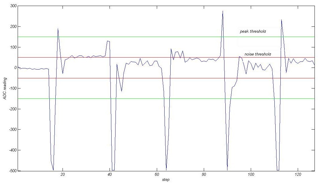
Figure 11: Acceleration Data of a Finger, Together with Noise and Peak Thresholds
Hand motion is found by detecting peaks of acceleration. For example, if the z-axis accelerometer on the back of the hand detects a large negative peak, then the hand is moving to the negative end of z-axis as defined in previous sections. The correspondence between peak sign and motion direction is summarized in table 2:
Besides, hand direction can be directly calculated if the hand is not moving and gravity is dominant. The acceleration with the largest magnitude will indicate which of the axes is in direction with the gravity. If hand moves in a different way than the previous direction, the new direction is the same.
Three different statuses are defined for fingers: straight, bent, and moving. Detection of finger status depends on hand motion and direction. If the palm is still and facing upward or downward, a finger must be straight if its z-axis acceleration is the same as hand z acceleration, and bent otherwise. For situations other than this, dynamic acceleration of the finger is used, since a rapid moving finger must produce a peak in acceleration. Therefore we set the status of an originally bent/straight finger to moving once a peak is detected, wait until the reading stabilizes to remove the “bounce” in acceleration, and set its status to straight/bent.
Through these simple methods, we were able to retrieve the information we need for the main state machine. Please note that slow finger motion can only be detected when gravity is a dominant acceleration of both hand and fingers, since we only used one axis accelerometers for the fingers.
3) Action Recognition State Machine
The action recognition state machine is the most important and complex component of our whole algorithm. Understanding constructing a state machine for more than 30 actions, which corresponds to more than 30 states, can be tedious and subject to error, we first set up a classification for the actions. Based on this classification, we used a mixed Mealy and Moore machine design to implement the main logic.
We divide hand actions into four groups: basic gestures, refined gestures, and actions. Basic gestures are the most general actions and only depend on current input. Refined gestures are same as basic gestures except that they have more restrictions on input, and these gestures are assigned meaning. For example, we defined gesture “aim” to be an input of straight index finger/thumb, bent middle finger and –X downward direction.
Actions are states that depend on the current input and previous state. For example, we define that if the previous state is “Aim” and the input indicates that the hand moves, the state changes to “Fire”.
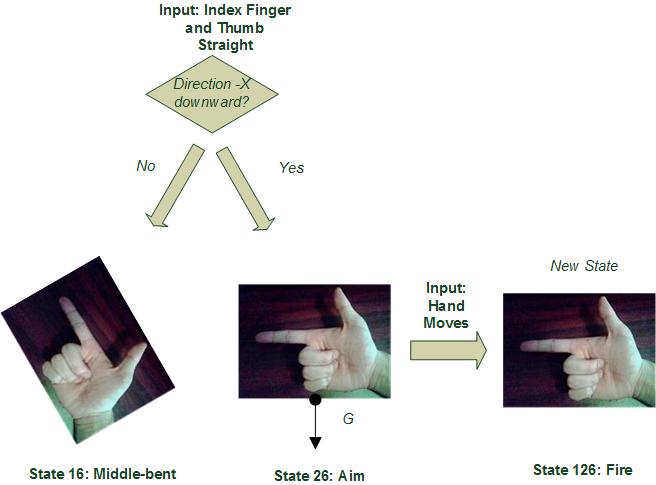
Figure 12: Refined Gesture “Aim” and Action “Fire”
To keep this action state library flexible and expandable, we keep a numbering convention: the index of a refined state is the index of its basic state plus a multiple of 10, the index of an action state is the index of the previous state plus a multiple of 100.
*REFERENCE TAKEN FROM CORNELL UNIVERSITY
 Posted in:

0 comments:
Post a Comment