About

This Blog is created for Embedded Systems Lovers irrespective of whether they are freshers or experienced. This blog gives a chance to everyone to learn new things and stay updated with the latest Embedded Technology. Articles, Tutorials, Project Source codes, PCB Layouts, Free Ebooks, and other free downloads would be available! The author is not responsible for any kind of mishaps,while developing applications. If you are not an expert in electronics, kindly take help from your seniors before starting with any of the projects described here. Hope you enjoy the Blog. Reader Comments would be highly appreciated !

Total Pageviews

MHCP Library !


MHCP App Library for MPLAB IDE can be downloaded here.


Show us some love, like us on Facebook: www.facebook.com/embeddedsystems

Free PIC Source codes Download ! PIC18F452

Here is a link for free download which contains PIC 18F452 source codes build in MPLAB IDE and Proteus Simulation files. Comments would be highly appreciated.

Here is the link:
FREE DOWNLOAD PIC SOURCE CODES

Show us some love, like us on Facebook: www.facebook.com/embeddedsystems

Solar panel based Lead Acid battery charger-DOUBT!

Hello people,
I have a doubt actually!
See let me explain you everything in a simplest way.
I have a solar panel (12V,0.5A). This solar panel is supposed to charge a Lead Acid battery (12V,2A).
I can understand that battery charging requires constant current and the current and voltage is supposed to be higher than that of the battery or else the battery would charge the Panel (Kidding!).

So friends, what I need to know is --
1. Firstly, is this actually feasible?
2. If yes, then how do I go about it?
3. Does Boost Converter come into picture anywhere ?
4. Do I need to include and inductor in the circuit?

I am unable to think of anything apart from the above mentioned steps.
Hope some of our intelligent visitors would help me out with it.

Show us some love, like us on Facebook: www.facebook.com/embeddedsystems

Looking for a DC to DC Boost Converter!

Here is the calculator for DC to DC Conversion parameters:

For many small projects, its cheaper and easier to DIY a boost converter than to buy a specialty chip. DIY converters are usually not as efficient but they're quick & cheap!
The above schematic section shows how I designed a 30-60V vacuum fluorescent tube display driven from a microcontroller pin.
Tubes such as VFDs, Nixies, Decatrons, etc require high voltage to light the gas in the tube. In order to reduce cost, we use a microconrtoller to make a boost converter and avoid paying $5 for a seperate chip. We can do this because we don't need a precision output and the current draw is mostly constant. The boost regulator is run open-loop there is no feedback resistor divider as it isn't necessary as long as the input voltage is within a reasonable range
The microcontroller runs at 8MHz so the 8-bit PWM output is 31250 Hz. The inductor and output capacitor is calculated below. The diode is a standard Schottkey type, but make sure you specify one that can handle the full voltage difference and peak current. The switch just has to be able to handle the max voltage plus some for safety. Note that this design is meant for 'static' output currents, not for variable current draw designs. There is no feedback and its very approximate! This is not for precision electronics!
The boost circuit works by connecting the power inductor L1 to ground that current can flow through it by turning on Q2. After a little bit of time, we disconnect the from ground (by turning off Q2) this means that there is no longer a path for the current in L1 to flow to ground. When this happens, the voltage across the inductor increases (this is the electric property of inductors) and charges up C6 . When the voltage increases to the level we want it to be (30V+) we turn on Q2 again which allows the current in L1 to flow back to ground. If we do this fast enough, and C6 large enough, the voltage onC6 is smoothed out and we get a nice steady high voltage
The timing of turning off/on Q2 allows us to modify the output voltage. Normally there is a feedback resistor to the microcontroller but it is not here because we are running it open-loop. To drive Q2 we use the PWM output from the microcontroller and adjust the duty cycle to vary brightness.
These sorts of designs can be easily made with a 555, once you have the PWM output, connect it up to Q2!
For this simple calculator, enter in the freqency, voltage ranges and current ranges and the duty cycle, inductor and current requirements will be displayed!
The calculator
Frequency
Hz
This is the boost converter frequency. For microcontrollers its often the CPU clock / 256
Min Vin
V
The lowest expected input voltage
Max Vin
V
The highest expected input voltage
Min Vout
V
The lowest desired output voltage
Max Vout
V
The highest desired output voltage
Iout
Amps
Output current draw
Vripple
V
Maximum allowable voltage ripple

Min. Duty CycleDmin = 1 - (Vimax/Vomin)
 %
Max. duty cycleDmax = 1 - (Vimin/Vomax)
 %
Min. Inductor sizeL > D * Vin * (1-D) / (freq * 2 * Iout )
 uH
Peak inductor currentIpk = (Vinmax * D)/(f * L)
 A
Minimum capacitorCap > Iout / (Vripple * freq)
 uF
Minimum Schottky diodeVbreakdown >= Voutmax & Idiode >=Ipk
 V  A
Don't forget that Duty cycle is the amount of time the switch is off / output is low. Be sure to measure the output voltages before connecting up anything important!
We like the J&W Miller / Bourns RLB9012 inductors and other thru-hole from the same company


Show us some love, like us on Facebook: www.facebook.com/embeddedsystems

Reference: www.ladyada.net

Need A Job? Join Stephen Hawking!


The salary is roughly £25k ($38.5k) and the start date is somewhere between 20 and 27 February 2011. 
Rate this news:   (0 Votes)
Saturday, December 31, 2011:  Well, if you have a superbrain that can be of help to the superstar physicist Stephen Hawking, you have clicked the right link. Stephen Hawking is looking for a geek to maintain his unique wheelchair. The celebrated author and cosmologist is offering a technical assistant job going, with a modest salary. The job requires you to maintain the electronic systems that allow him to speak in public and meet others in the world of Physics.

The selected candidate will be working for one of the University of Cambridge's top theoretical scientists...yet performing rather practical tasks. 
Stephen Hawking, Assistangt to Stephen Hawking, Universoty of Cambridge, Stephen Hawking

Hawking suffers from a motor neurone disease, which has made him almost completely paralysed. He relies on his souped-up wheelchair to get out and about, and various bits of gear to translate small hand movements into words, spoken in the monotonic robotic voice that - outside the arena of particle physics - he is best-known for, said a report from The Register.

The unconventional job advertisement which informs about the job goes like this, “It is not a PhD or post-doc position for academics looking to study physics, but a purely technical post to allow Prof Hawking to function within the physics community and as a public speaker. The original purpose of this position was to aid Professor Hawking in those areas which he has difficulty due to his disability. The job has since expanded."

The role of 'Graduate Assistant to Professor Hawking' is being funded as a research post at the University of Cambridge. Normally it has been under a 12-month contract, although recent graduate assistants have stayed on for several years. The salary is roughly £25k ($38.5k) and the start date is somewhere between 20 and 27 February 2011.

Click here to apply for the job. 
Show us some love, like us on Facebook: www.facebook.com/embeddedsystems

Welcome People!

It is being noticed that we are getting traffic from almost every part of the world. Thank you for visiting us people.
Want to stay updated to the latest articles on Embedded Systems World?


 Join us on FACEBOOK !!

ARM becomes processor of choice for embedded modules


Congatec is the latest embedded computer module firm to increase its dependence on ARM processors.

A major user of x86-based processors from Intel and AMD in its modules, congatec says it now plans to increasingly use ARM technology. 
As a result it will use Freescale's ARM-based i.MX portfolio of products. As a first step congatec is expanding its Qseven product family with Freescale processors. 
Embedded computer module suppliers Kontron and MSC already have ARM-based products.

According to congatec, the latest ARM processors will support the PC interfaces needed in computer-on-module (COM) product design.
The COM concept integrates all generally available interfaces onto the computer module itself while any special interfaces are implemented on individually-tailored carrier boards.

In contrast, the majority of existing ARM processors come with specialised interfaces designed to suit dedicated applications.

"These cannot be used by COMs in a standard format and are therefore neither interchangeable nor scalable. However, the new generation of ARM processors focuses on standard PC interfaces such as USB and PCI Express and will therefore be ideally suited to COMs," said congatec.
The Qseven specification was updated in September 2010 (Revision 1.20) to enable the development of 100% compatible ARM-based modules.

“In Freescale, we have found a reliable partner with whom we will be able to meet the requirements of our customers with regard to operating system support and long-term availability,” said Gerhard Edi, CEO of congatec AG.

According to Henri Richard, senior v-p of sales and marketing for Freescale: "Our next generation i.MX products will be introduced into applications more quickly and easily thanks to congatec’s Qseven modules.”
The first products resulting from the Freescale collaboration are expected to be available by the middle of 2012.


Show us some love, like us on Facebook: www.facebook.com/embeddedsystems

PIC microcontroller with inbuilt RF and works on 1.8V


Microchip integrates low power PIC with RF transmitter


Microchip has integrated a low power 8-bit PIC microcontroller with a sub-GHz RF wireless transmitter. 
The device is also optimised to run Microchip’s royalty-free KEELOQ advanced code-hopping technology for secure links.
Aimed at remote keyless entry fobs for automobiles, garage doors and home security systems, the PIC12LF1840T48A device comes in a 14-pin TSSOP package.
With an operating voltage of 1.8V, the device is designed for low sleep mode current consumption, and is integrated with the transmitter in a way to enable fast wake-up and send functionality that takes advantage of the MCU’s 8 MIPS operation.
Application note AN1393 ‘Using the PIC12LF1840T48A Microcontroller with integrated sub-GHz Transmitter’ is available for download today, to assist engineers in developing remote-control designs.
The chip is sampling and volume production is expected in January.


Show us some love, like us on Facebook: www.facebook.com/embeddedsystems

4 year Old Engineer

This 4-1/2 year old future engineer demonstrates how easy it is to program the NXP LPC1768 ARM Cortex-M3 microcontroller using the mbed rapid.
Kindly have a look at the video here:
http://www.youtube.com/watch?v=ZkK9zUM0Jlw 

Show us some love, like us on Facebook: www.facebook.com/embeddedsystems

Short Range RADAR System for Home Security

The idea to create a type of close proximity radar system came from a student in one of my classes. We went ahead and decided to streamline the idea into the course as one of the projects we'd build. 
           After a week or two of prep time we finally agreed on the project setup & parts that we'd use. This is not meant to be an advanced project, thusly the difficulty is set at medium. 

           Below is an example of what short range personal radar could be used for. It's meant to be a bit comical so feel free to laugh! 


Purpose & Overview of this project
           The goal of this project is to create a working ir radar system. The system will only be required to measure close proximity at an angle of 90 degrees as seen in the example above. The range of system is roughly 4-30cm, 20-150cm & 1m-5.5m depending upon which sensor you choose to use. 


           The outcome of this project will shape future projects where we try to integrate such a radar system to help navigate mobile robots through the real world.


Parts List Details
           You may or may not be familiar with the parts above so a picture of each item has been included to help give you an idea of what they look like. Three new objects that we've never seen before appear in this project; Servos, the74HCT373 & IR Sensors. Tutorials on Servos & IR Sensors should be up soon but for the 74HCT373 I've given a brief overview of it below. You can always check out the datasheet for the chip by search google for "74HCT373".

74HCT373
 
The 74HCT373
           This chip is an octal d flip-flop tri-state latch. In english that means that this chip is capable of storing 8 bits of digital logic and holding that memory until it is cleared or changed via the LE-Latch Enable pin.

How It Works
     •Control Pins LE & OE
     •8 Data Inputs D0-D7
     •8 Data Outputs Q0-Q7
     •Vcc & GND.
           Output Enable allows Q0-Q7 to output the data currently held in the D-FlipFlop Latches.
           Latch Enable enables the data currently on D0-D7 to overwrite whatever the D-FlipFlop Latches currently have.


Schematic Overview
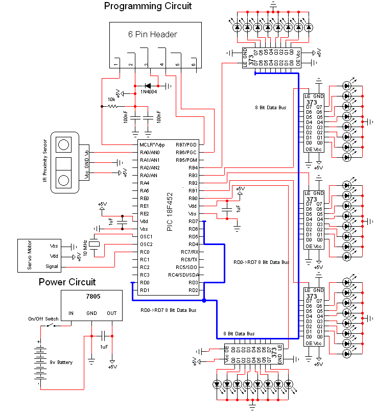
           The schematic for this project is much more complicated than previous projects. There are four main features in our design. (1) We will be able to program the pic on the board we develop. (2) We will be controlling a servo. (3) We will be taking data input from an IR Proximity sensor. (4) We will set 36 LEDs to display proper output to respresent what the IR sensor sees.


View Full Schematic

Schematic Specifics
•Power Circuit
           The power circuit is a 9v Battery hooked up to the LM7805 with a 1uF capacitor hooked to output & ground of the LM7805 to keep a steady 5v DC.
•Programming Circuit
           The programming circuit is made by hooking up two pins from the PIC to the programmer and allowing the programmer's pin 1 access to the MCLR*/Vpp-Pin1 on the PIC. We put a rectifier diode in there for safety as well.
•IR Proximity Sensor
           The IR Sensor only uses 1 pic from the pic, PIN 2 - RA0. It will use the analog feature of this pin to get an ADC value as the proximity sensor only outputs analog voltages. This value will tell us the if anything is near the sensor in our enviornment.
•LEDs Output
           There are 40 LEDs in total. Since each 74HCT373 can control up to 8 leds; 40/8 = 5 we'll need to use 5 74HCT373's to be able to control all 40 LEDs. It is important to notice on the schematic that a common data bus is used between all the 5 chips.


The Theory
           This project uses three main devices to create the personal radar system. The IR Range sensor gives output, the pic microcontroller processes it and then displays the output on the led array. Here is a simple little animation that demonstrates this:


Using Different Sensors
           An interesting thing about the sharp IR sensors that I've used in this project is that they all follow the same voltage curve so one program can literally fit all sensors. You only have to be aware of the sensor that is being used to make sense of the distance output by the leds.

Our Implementation
           We just got a brief high-level overview of the theory, for more indepth explainations of the theory please go back to any of the tutorials (pic, servos orir sensors). Now let's take a look at the finished hardware device:


           This is how the device looks when it is completed. So let's move onto the next section and actually assemble the schematic on the proto board and build the hardware enclosure.


Hardware Design
           The plastic enclosure seen below wasn't mentioned in the parts list. It's just a generic enclosure you can buy from any electronics distributor or manufacturer.

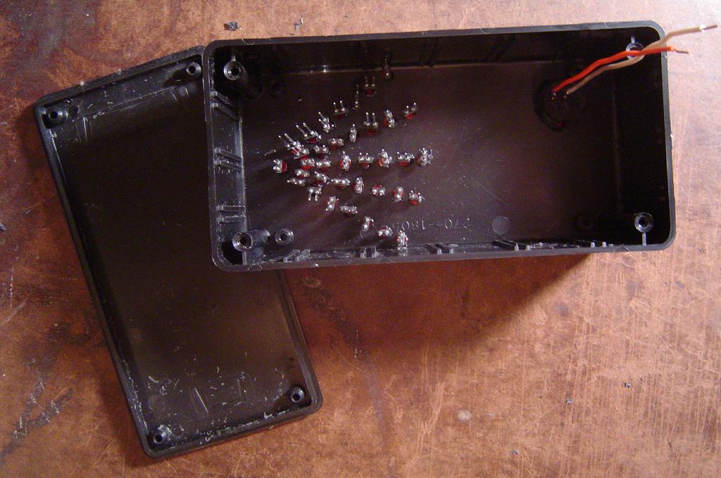
           The first thing we need to do is to drill holes for all the 36 leds that will be in our circuit and to e-poxy the leds into them. Additionally I put a little epoxy on led leads before sticking them into sip sockets so they'd stay on.


           Now we'll get the board soldered in and start to wire-wrap the schematic. You should be able to fit all the ic's onto the board in a small enough space to fit into your enclosure.


           The above picture is a sample of how the board should look during initial stages. Once you have everything wirewrapped it will be quite a mess of wires but should look something like this:


           The final look at the hardware design is what allows the personal radar system to be used 'remotely'. We use a length of wire about 2-4 meters long when connecting the servo & ir sensor. We put a hole in the front of the enclosure for these wires:


With the hardware completed lets move onto the software portion of the project. This is definitely the funner part of this project, nore more soar fingers from wire-wrapping. 


The Software
           The IR range software for this project has three main portions to it.
    -Servo Control
    -Led Output Control
    -A/D Input

           Since the software for this project won't fit all on one page I'll explain these three elements and how they're implemented. If you have any lasting questions about the software just go to the forums and ask! The program is heavily commented so it should be readable.

Servo Control
           The method used for servo control is via timers & interrupts. A 50Hz signal is generated by two seperate interrupts that work together to create desired pulses that make the servo pan left and right in small steps so as to quiet the servo's squeaking movement noise. 

Led Output Control
           The leds are all controlled via the 74LS373/74HCT373 latches. The pic inturn controls these devices by switching the control lines. The system constantly updates the latch information which can be seen by the led output. 

A/D Input
           The IR range sensor output is in the form of a varying analog voltage. We use the a/d converter to find the value of this voltage which will tell us the distance that objects are away from the ir range sensor.


           Software loaded & hardware completely built. Let's test it out! Depending on the sensor you use, different output will be visible on the leds. Sensors to choose from: GP2D120, GP2Y0A21YK or GP2Y0A700K0F.


Data & Observations
           The first test of the personal radar system will be close range. I used rockstar energy drink cans as obstacles. (These IR sensors work best when objects are all white.)


           The second video (which was seen on the first page) tests out the 20cm-150cm & 1m-5.5m sensors which allow for funner things than rockstar can obstacles. Watch and you'll see what I mean:


           These two videos give you a good idea of how well the sensor can work, however if you build it yourself you'll see a few shortcoms which I'll discuss in the conclusion. 


Program Download:

Main C File 
ir_range_project.c

An Overview Of The Personal Radar System
           Building and programming this project doesn't take too terribly long. It is definitely a project that you can complete in a day and it has some viable uses but in the long run there are many shortcommings that arise from using this form of radar. IR sensors can become unreliable and rarely output constant results because of ambient and enviornmental light.


What To Do Now
           If you really want to improve upon this form of radar a good area to explore would be the use of ultrasonic sensors. Ultrasonic sensors are the equivalent of above water 'sonar' sensors that will tell you the range an object is away from you. Ultrasonics have a greater range than Ir sensors and are typically far more reliable in unfamiliar enviornments. 
Source: http://www.pyroelectro.com/projects/ir_radar/ 

Show us some love, like us on Facebook 

Techlligent 2012 - A National Technical Event !

 TECHLLIGENT - An Indian National Technical Fest ! will now be held in Pune. This would be a Golden opportunity to those who can show up their talents. This event would include competitions for almost all the branches.

ON 17th and 18th FEB 2012

For Electronics maniacs, the list of Events would be :
Matlab Madness
Race the Dexter
Byte the Bit
Electronica
Design on the Spot
Inter Disciplinary

Pimpri Chinchwad College of Engineering,
Near Akurdi Railway Station, Sector No. 26,
Pradhikaran, Nigdi,
Pune – 411 044
Website: www.pccoepune.com

 So guys kindly take full advantage of this wonderful opportunity and each one of you try to participate because participating in national events would definitely be a PLUS when you appear for an interview.

COMMENTS OR QUESTIONS WOULD BE HIGHLY APPRECIATED !

Show us some love, like us on Facebook


Best Electronics Ebook Free Download

I was just surfing through the internet and I came across an ebook. I am usually not very fond of reading and not especially Ebooks. But believe me, this particular book is to the point. I had no interest in transistors because whenever I start reading about a transistor, I had to start with holes and electrons.
If you still dont believe me, just go through the Transistor As a Switch Section and let me know if you dont understand.

DOWNLOAD HERE


Show us some love, like us on Facebook: www.facebook.com/embeddedsystems

Laser Show using microcontroller


Laser show for poor man
i
  • 2282454805_7d9c0d0842.jpg
  • 2283233610_5e2b07c4dd.jpg
  • 2283271604_7390fed3cf.jpg
  • 2282439469_2749052066.jpg
  • 2283243264_6515d62e83.jpg
Here's another useless but cool looking "must build" gadget for every romantic geek.
Let me introduce PIC microcontroller based three axis laser spirograph.


...

...

Step 1Gathering stuff

Gathering stuff
i
Design is quite simple and employs regular parts and components but you are free to change/modify it in way you like.

Originally I'm very lazy man so I've chosen programmed microcontroller PIC18F1220 (can be replaced with PIC18F1320) to handle routine job.

PIC implements 3 channels PWM generator.

PWM signal toggles MOSFET transistor 2N7000 (Id 200mA). Mirror actuator is connected as load to MOSFET.
As mirror actuator I used 5V 200mA CPU cooling fan. It's easy to mount mirror on its flat side.
Device accepts 5V and 12V fan with maximum current 200mA . Voltage is selected by jumper.

Green laser pointer is rated at 3V so I've made LM317-based voltage regulator with adjustable output.

Cheap 5mW green laser module:
http://www.dealextreme.com/details.dx/sku.10094~r.32746761

What else will you need?
Dozen of resistors and capacitors, potentiometers, toggle switch, power jack, prototyping board, box of proper size and power supply unit.

Step 2Brain

Brain
i
Electronic schematic is simple and can be assembled on a prototyping board but real man always makes troubles for himself, so I've made PCB.

There are two work modes, selected by toggle switch: manual and automatic.
In manual mode operator controls each motor individually by twisting corresponding potentiometer connected to analog input of microcontroller. PIC constantly reads analog inputs and modifies PWM signal so duty value is proportional to voltage on analog input.
In automatic mode microcontroller employs pseudo-random algorithm to calculate duty value for every motor.
Current duty value is stored in internal EEPROM and used as initial data for next calculation
so microcontroller will generates sequence of nonrepetitive unique patterns for long time.

Most pointers are rated from 3V to 4.5V, so make sure you adjust output voltage before connecting laser.

Board is small, so you don't need any brackets to secure it. Pots will hold it perfectly.

UPDATE NOTE !!!
Since my supplier run out of PIC18F1220, I had to use PIC18F1320 in new design.
It's pin-compatible chip with increased memory capacity, but it will NOT work with old HEX file,
so pay attention.
I keep PIC18F1220 version as separated file.

Here are some notes from the bench:
- schematic;
- BOM;
- HEX (PIC18F1320 version);
- PCB;
- PCB in AutoCAD format
- source code for CCS compiler.


Documentation zip file


To program chip, I use USB ICD2 programmer (bought it from eBay) and MPLAB IDE (free soft from Microchip.com).

PCB contains standard Microchip ICSP port (5-pins header) for programming purpose, also chip can be programmed by any socket programmer with proper software which supports PIC18.

Controller board assembling (high res guide):
http://www.flickr.com/photos/22144851@N03/sets/72157604945292921/

...
For beginners and busy people, programmed chip, PCB, whole kit, or assembled board available upon request.
...

Some hobbyists may prefer simplified analog PWM controller based on 556 timer.

Step 3Spirograph controller V2.

Spirograph controller V2.
i
  • v2-spirograph-1.jpg
  • 100_3333_l.jpg

UPDATED VERSION!!!

New controller board is completely redesigned with use of SMT components.
5V switching voltage regulator eliminates needs for heatsink.  As result controller has became 1.5 times smaller and that provides possibility of making truly pocket version of spirograph.
Embedded voltage regulator for low power laser module provides power within 2 - 4V.
Controller supports 5V and 12V fans. Fan voltage can be set by wire jumpers on board.

Along with auto and manual modes of operation modified controller has ability to store your favorite patterns in internal memory with just press of a button and replay them as a slide show.
New controller can store up to 80 user defined patterns and replay them as endless sequence. Time of showing  single pattern can vary from 3 to 60 seconds. Also there's manual mode when next pattern in sequence is triggered by a user.

Descriptions of new controls.

Switches:
PROG/CYCLE - selects PROGRAM (manual)  or CYCLE (auto) mode of operation.
RAND/MEM - selects subroutine to generate random pattern or reading stored patterns from internal memory.
CONT/STEP - selects CONTINUOUS or STEP mode of showing sequence of patterns.
This switch is active only in MEM mode.

Button STEP/MEM:
 - in PROG or CYCLE/RAND modes button writes current pattern in internal memory. Stored patterns can be displayed as slide show in CYCLE/CONT mode.
 - in CYCLE/MEM/STEP mode button cycles trough sequence of stored patterns.
If button is being held pressed during powering up all internal memory will be cleared.

POT A:
 - in PROG mode defines speed of motor 1.
 - in CYCLE/MEM/CONT mode defines time interval ( from 3 to 60 Sec) of showing single pattern from sequence.
POT B:
 - in PROG mode defines speed of motor 2.
POT C:
 - in PROG mode defines speed of motor 3.

Description of operation.

There are two working modes : PROGRAM (manual)  and CYCLE (auto).
In PROGRAM mode, pattern being displayed depends on positions of potentiometers.
Current pattern can be saved in internal memory by pressing button MEM. After 80 patterns have been stored, each new pattern will substitute the oldest pattern.
To clear memory press and hold MEM button during powering up.

In CYCLE mode, unit displays endless sequence of pattern.
In CYCLE/RAND mode, patterns are randomly generated by software. Initial positions of pots determine shape of the first pattern in sequence. Current pattern can by saved in internal memory by pressing button MEM.
In CYCLE/MEM/CONT mode, unit continuously reads patterns to display from internal memory. Time interval for displaying single pattern depends on position of POT A and can vary from 3 to 60 sec.
In CYCLE/MEM/STEP mode, reading of next pattern from memory is triggered by button STEP.
All technical notes such as
- schematic;
- PCB in PDF format;
- BOM;
- HEX file for PIC18F1320;
- C source code for CCS compiler.

can be downloaded from here

Upon request I can provide assembled SMT controller, mirrors and other stuff for this project.

Step 4Attaching mirror to the motor

Attaching mirror to the motor
i
UPDATE!!!
---

---
Acrylic mirror is very light, so double sided sticky foam tape will do job.
Piece 1/2 x 1/2 is working good.

You can use thick paper as a wedge to tilt mirror. Insert it between mirror and motor.
In my setup tilt is 2-3 degrees. It results 6' wide pattern at a distance 18'.

It's impossible to center mirror properly regarding motor shaft and even slight offset will cause
vibration and noise at high speed, so I've developed some tricks for mirror balancing.
Make sure your safety glasses still on.

WARNING!!! This method will work only for acrylic/plastic mirrors!!!

At first I've tried to shape spinning mirror with file but fan is low torque device, so even light pressure with tool forced motor to full stop.

Since idea with turning part and fixed tool has failed, I've tried opposite approach -
Dremel with 1/2" sanding drum against motionless mirror, and that's really worked.

Some advices for people who wants to follow.

Motor with mirror must be off.
Select sanding band with coarse grit.
Set Dremel to minimal speed.
Hold Dremel that axes of tool and motor shaft are parallel.
Slowly bring sanding drum to the edge of mirror and press against it. Don't put much pressure. Spinning tool will rotate mirror and file it at the same time.
Take your time, go easy and, if you have enough patience, you'll get perfect round mirror which will run smooth and quiet.

Step 5Parallel optical setup

Parallel optical setup
i
  • 2164589055_df24a4d213.jpg
  • 2165390158_cc444cc800.jpg
  • 2164594425_6ed025294c.jpg
Classic setup.

Motors are placed on parallel lines.

I've developed one trick. I use double sided sticky tape to attach motor to base, and after all adjustments I secure motor on place with hot glue.

Adjustment is simple.
Start motors and aim beam that it stays within mirror area at maximum deflection.

As support for pointer I use piece of wood and some hot glue. Cheap and fast.

Step 6Square optical setup

Square optical setup
i
  • 2273284613_db36875cdc.jpg
  • 2273285703_bc92e11a7b.jpg
  • 2274082690_7b376629cd.jpg
  • 2273288127_8f7ae48c09.jpg
Square optical setup. I like it better.

Motors form square without one side.

Using this design we can make more compact device.

Everything else is the same as previous step.

Step 7Let's build tiny house

Let\
i
  • 2165383168_bcb5b3691d.jpg
  • 2165383744_4bc93d0364.jpg
  • 2164590047_925eea4613.jpg
It's a good habit to keep dust away from optical staff, so our device needs hermetic enclosure.

I had Hammond 7x4x2 box lying around, so I put it in business.

Since we determined optic configuration and beam path we can mark and cut out window.
Then get square piece of transparent acrylic and glue it to its place.
Next drill one more hole for power jack, glue it, connect to board and we are done.

Step 8Well done

Well done
i
  • 100_1085.JPG
  • 100_1371_l.jpg
  • 2283205090_c665b77b33.jpg
  • 100_2782.jpg
Not bad, not bad, but I would add something spicy.

...Aluminum faceplate and secret military technology of heat toner transfer!!!

That makes real difference.

Now I'm happy.

Step 9Laser spirograph V2 completed

Laser spirograph V2 completed
i
  • V2-performance.jpg
  • V2-mounting-1.jpg
  • V2-mounting-2.jpg
  • V2-mounting-3.jpg
  • V2-completed-1.jpg
  • V2-completed-2.jpg

New version of PIC based laser spirograph.

To make device more compact I've modified design by adding one more mirror.
Now optical components occupy less area and all parts can be fitted in standard 4" x 4" x 2.5" Hammond project box. 

Aluminum faceplate and background illumination are optional. 


Show us some love, like us on Facebook: www.facebook.com/embeddedsystems

Reference: Instructables !

Twitter Delicious Facebook Digg Stumbleupon Favorites More

 
Design by Free WordPress Themes | Bloggerized by Lasantha - Premium Blogger Themes | Colgate Coupons